Figure 5
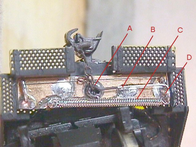
At the right side about 1/16" in from the end and centered vertically is a pivot point. (Fig. 4-C) It is a wire soldered into the PC board and sticking straight up from the board. At the left side is an anchor point. (Fig 4-A) It is a wire soldered into a hole at the lower left corner of the PC board and bent over parallel to the board surface and sticking forward (up) towards the end of the engine. It may be bent from side to side to adjust the tension on the Muscle Wire. About 1/8"-1/4" closer to the center of the loco, but also on the lower left side is a second anchor point. This is for the return spring, and just sticks up like the pivot does, but shorter. (Fig. 4-G)
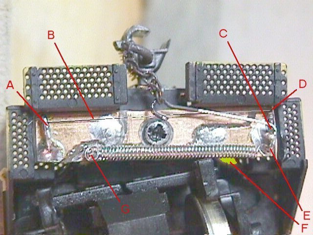
The actuator arm is a "T" shape with a small hook formed at the bottom of the "T". (Fig. 5-B) I bent these from .045-.048 guitar string. The cross bar of the "T" is shorter than the width (front to back) of the PC material, and it droops down a bit on one side to hook over the pivot point. The bottom leg of the "T" reaches from the right hand pivot to the center of the coupler pocket, with the center of the hook loop directly over the mounting screw. (Fig 5-A) Form it this way: Cross the top of the "T" from left to right. Bend a "U" in the end (Fig 4-E) for the return spring, (Fig 5-C) and then back across the top to just past center. Then turn a right angle down around the pivot point to near the end. Finally make an almost closed loop for the chain. The loop should center over the mounting screw. (but clear it) This allows the coupler to swing with no change in the length of the chain. A small blob of solder (Fig 5-D) near the loop keeps the "T" bar positioned correctly on the pivot.
Figure 5
"Muscle wire" (100 micron) (Fig 4-B) from Jameco at http://www.jameco.com/ is connected from the upper (loco coupler end) side of the "T" arm (Fig 4-D) across the width of the loco to the left fixed anchor. (Fig 4-A) Wind a spring from .009 guitar string (Fig 5-C) and connect it from the lower side of the "T" arm (Fig 4-E) to the spring anchor. (Fig 4-G) Wind the .009 wire close spaced around a 1/16" drill bit shank. I chucked the drill in reverse in my pin vise with the drill flutes just visable. Stick the end of the wire into a flute to hold it and commence winding till you have about 3/4" of spring. You want about 50 grams of tension when you are done. Cutting the spring length such that it is stretched out about 20% when it is installed should come close enough. Clip the wire, and form the ends as shown above. (Form one loop up, and the other down.)
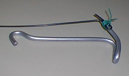
Figure 9. Lashing the Muscle Wire to the "T" bar.
This 20:1 scale model of the actuator shows how the Muscle Wire (black) is lashed to the "T" bar. (silver) The lashing (green) is done with a single strand of wire taken from a piece of decoder lead wire. Be sure a turn of the lashing feeds through the bight (fold back loop) of the Muscle Wire. Twist the ends together and solder the lashing to the "T" bar. Pull the end of the Muscle Wire to close the loop. Clip off the twist after soldering. Do not expect the solder to stick to the Muscle Wire. This is strictly a friction attachment.
When you pass 180 ma through the "Muscle Wire" it heats and changes crystal state causing it to shorten. When the current is removed it relaxes, and the spring can stretch it out again. This action rocks the "T" bar on it's pivot. Because the long leg of the "T" is about 5 times as long as the cross arms, the small length change in the "Muscle Wire" is multiplied to a usable throw.
Because the "T" bar is electrically connected to the decoder you will need to dip the hook end in either liquid electrical tape or enamel to insulate it from the chain. (I experiment with the newer plastic couplers, but they did not work well at all.) Hook the chain over the hook of the "T" bar. (Fig 5-A) One electrical connection is the left anchor point. (Fig 4-A) The other is the spring anchor and pivot point. (Fig 6-F) Cut gaps as shown in the copper foil between the two connections. (both sides if you have double sided material.) Also be sure to prevent any contact between the mounting screw and the foil. A section of foil is directly under the spring to connect the spring anchor electrically to the pivot point. (Fig 6-F)
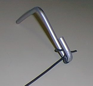
Figure 10. Constrictor knot for attaching to the
anchor point.
The fixed anchor is formed as shown above from a piece of 1/4W resistor lead soldered to the PC board. Tie the other end of the Muscle Wire to the fixed anchor using a constrictor knot. (shown in the inset above) After adjusting the wire length such that the "T" bar is in approximately the correct position, squeeze shut the fold back, and touch it with a bit of solder to prevent the Muscle Wire from sliding from side to side, or slipping loose.
Touch a bit of solder to the ends of the spring where it contacts both
the spring anchor and the "T" bar to guarantee a permanent electrical connection.
Bend the tip of the "T" bar pivot a bit to prevent the "T" bar from slipping
off, then trim both the "T" bar pivot and spring anchor to length. Adjust
the "T" bar position by bending the fixed anchor wire back and forth till
all the excess slack is out of the chain, but the coupler can still swing
freely without opening the knuckle.