Introduction
One of the functions often included in a layout is a hidden staging area from
which we can pull trains for a run on the visible portion of a layout, then
store them away again. The operational problem with this is that the trains
are not only hidden to the visitors, but often also to the operators. This
circuit will allow the operators to put trains into a staging area and have
them automatically stop when they reach the end of the tracks.
Background
In the days of DC operation it was a simple matter to isolate a section of
track at the end of a staging section with a diode. This would stop an engine
from going further, but still allow it to be reversed out again. DCC does not
allow this, so we must simply cut the power to the storage track at the proper
time, then restore it again to reverse the train.
How It Works
The TC-64 lines each include the option to send or respond to an auxilary command. By causing the end of storage track detector to send an 'Off' command to the track power relay we have an easy way to link the power off to the detection of a train. Resistive wheel sets and current detectors, or else photo sensors will assure that trains can pull, or back, into the storage tracks. This actually works better than the old DC diode trick, which required the engines to always be at the dead end of the tracks.
Problems
The power must be cut to the entire storage block, not just a small section at the end to allow multi-unit engines to stop properly. Power is maintained on all units until the train reaches the stopping point. It is then removed from all the units at the same time. This even allows helpers on the trains.
Another problem is that simply removing all power would disable current detection
and there would be no more indication that the storage track was occupied.
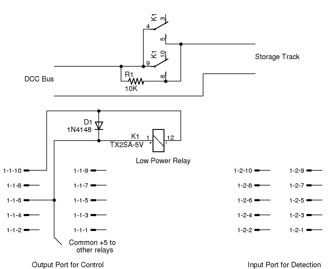
Simply adding a 10K resistor across the relay contacts assures that sufficient
current flows to maintain block detection.
Advantages
The advantage of using the TC-64 for this operation is that it alllows the operation to be event driven. It opens the relay as the detector becomes occupied. However it does not prevent the relay from being closed again to pull the train out of the storage track, even while the end of track detection shows occupied. I suppose that a complex latching circuit could be devised to do this, but with the TC-64 it is simple. Only send the 'Stop' command when the block becomes occupied. Ignore the fact that it becomes unoccupied.
.
The Wiring
Set the output (control) port to Type 'Driver'. Set the input (command) port to be 'Detector'.
Connect the track power control Relays as shown below.
Use only the specified relay which is a special low current relay that may be
driven directly from a TC-64 output port. Only one of 8 possible relays is
shown in this diagram.

Port Settings
The following screen shots show the modifications required to the normal port
settings to make this work.
(click to enlarge images)
The Parts
K1 Relay TX2SA-5V
D1 Diode 1N4148
R1 10K ohm
-1.png)
.png)