Introduction
One of the common signals from the mid 20th century was the
searchlight signal. Many companies have created model versions of these
signals over the years. The problem has been lighting them
realistically, especially in the smaller scales.
Background
The usual method that is chosen to light these signals is to use a
dual color (red/green) LED and take advantage of the fact that the eye
will blend the red and green into a yellowish color when they are both
lighted.
How It Works
In order to get these blended colors both the red and green must be
lighted at the same time, or nearly enough that the eye can not tell.
For the three lead version of the two color LED this is not too
difficult because each LED has its own connection. However one common
two color LED uses reversed polarity to light one color or the other.
To drive these LEDs a circuit must be devised to rapidly reverse the
polarity driving the LEDs. We created the SDB-4 board especially for
this purpose.
Problems
In spite of having an adjustment that would allow the user to easily
change the proportion of red and green colors it was still nearly
impossible to create a realistic yellow color, especially as the user
would move his vantage point. This was mainly due to the fact that the
front of a LED is actually a domed lens, and the two color chips are
not possible to mount at the same location internal to the LED. This
means that as the viewer moves his head he sees more or less of each
chip at the focal point of the lens. More simply put, he sees the red
or green more in focus from different view points. The only way to get
a good yellow is to use just one eye, and only from a fixed position.
Solution
The solution to this is obvious. You need to have a three color LED, not a two color LED. Unfortunately all the readily available three color LEDs that are small enough to fit into a small signal head are the primary light colors of Red, Green, and Blue, not the signal colors of Red, Green, and Yellow. Furthermore the primary color green and the RR signal green are not the same. To solve this issue we contacted a major LED manufacturer and special ordered a three color LED. Because it was a special order in the first place we were able to also specify the proper colors for each LED.
Advantages
 The advantage of using the three color LED is that not only do you get
the proper three colors, but the wiring is the same as it would be for
any other three color signal. The disadvantage for us as a manufacturer
is the difficulty and time required in soldering four very small (#36AWG) wires onto a 3mm
diameter circuit board that has the LED mounted on it.
The advantage of using the three color LED is that not only do you get
the proper three colors, but the wiring is the same as it would be for
any other three color signal. The disadvantage for us as a manufacturer
is the difficulty and time required in soldering four very small (#36AWG) wires onto a 3mm
diameter circuit board that has the LED mounted on it.
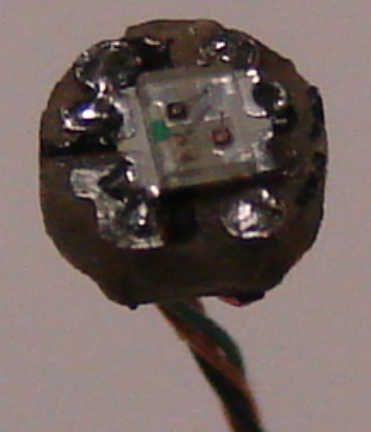
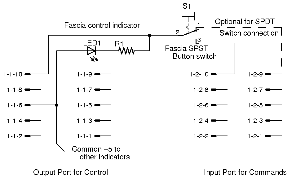
The Wiring
The wires to the circuit board are color coded red, green, amber,
and dark blue. The dark blue wire is the common anode connection.
Images
The following images show our 3 color LED mounted into a simple
Oregon Rail Supply signal head as compared with another popular
searchlight
signal. In these photos both signals are being driven from identical
circuits at the
same current. (4ASD-4) The black chunk is the original sprue which I
did not remove. The 3mm circuit board was simply inserted into the rear
of the Oregon Rail Supply head. It could just as well have been
inserted into any other head with sufficient opening for a 3mm LED.
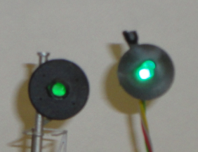
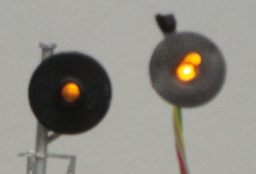
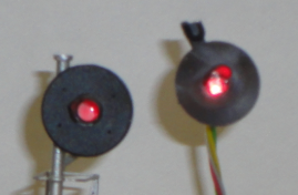
The reason the 3 color LED appears to be so much brighter, even
washing out the colors in these photos, is that you are looking directly at the chip.
The other signal has to locate its individual LEDs down inside of the
housing for sufficient space, and then reflect the light through a
clear plastic light pipe to the front of the signal.
The Parts
RR-CirKits SS-RGY-18 LED with 18" #36AWG color coded wires.
Oregon Rail Supply #102